
The anti-lock braking system (ABS) monitors the parameters of the vehicle's movement according to the readings of sensors installed on one or more wheels. Learn about what an ABS sensor is and why it is needed, what types it is, how it works and on what principles its work is based - find out from the article.
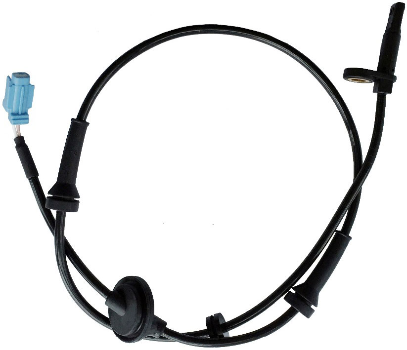
What is an ABS sensor
ABS sensor (also automobile speed sensor, DSA) is a non-contact sensor of the speed of rotation (or speed) of the wheel of vehicles equipped with various electronic active safety systems and auxiliary control systems. Speed sensors are the main measuring elements that ensure the operation of the anti-lock braking system (ABS), stability control system (ESC) and traction control. Also, sensor readings are used in some automatic transmission control systems, tire pressure measurements, adaptive lighting and others.
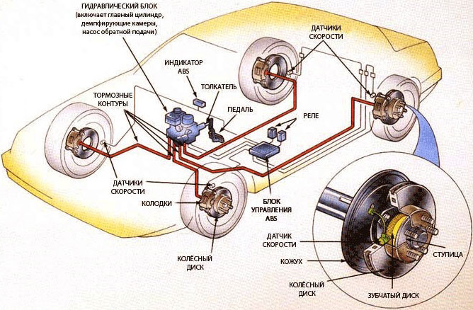
All modern cars and many other wheeled vehicles are equipped with speed sensors. On passenger cars, sensors are installed on each wheel, on commercial vehicles and trucks, sensors can be installed both on all wheels and in drive axle differentials (one per axle). Thus, anti-lock braking systems can monitor the condition of all wheels or wheels of drive axles, and based on this information, make changes to the operation of the braking system.
Types of ABS sensors
All existing DSAs are divided into two large groups:
• Passive – inductive;
• Active — magnetoresistive and based on Hall sensors.
Passive sensors do not require external power supply and have the simplest design, but they have low accuracy and a number of disadvantages, so today they are of little use. Active ABS sensors need power to work, are somewhat more complex in design and more expensive, but provide the most accurate readings and are reliable in operation. Therefore, today active sensors are installed on most cars.
DSA of all types have two versions:
• Straight (end);
•Corner.
Direct sensors have the form of a cylinder or rod, at one end of which a sensing element is installed, at the other - a connector or wire with a connector. Angle sensors are equipped with an angular connector or a wire with a connector, and they also have a plastic or metal bracket with a bolt hole.
Design and operation of ABS inductive sensors
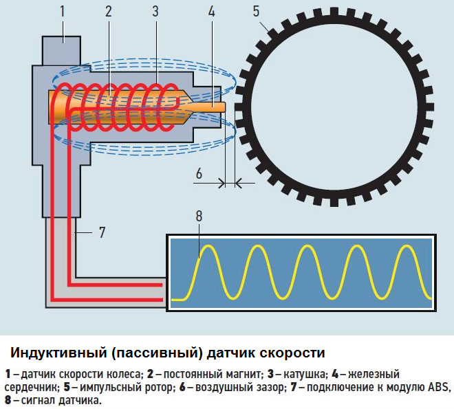
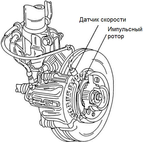
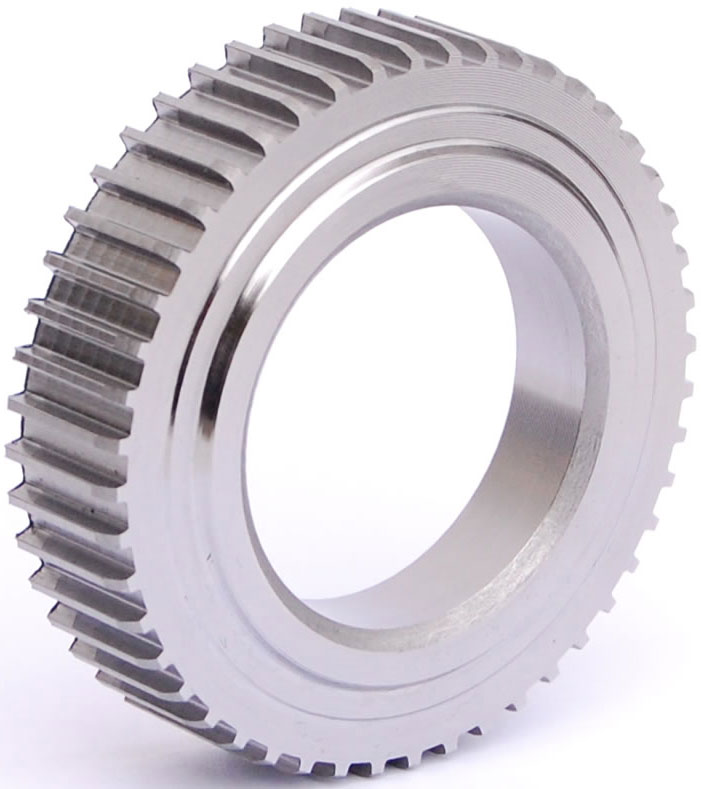
This is the simplest speed sensor in design and operation. It is based on an inductor wound with a thin copper wire, inside of which there is a fairly powerful permanent magnet and an iron magnetic core. The end of the coil with a magnetic core is located opposite the metal gear wheel (pulse rotor), rigidly mounted on the wheel hub. The rotor teeth have a rectangular profile, the distance between the teeth is equal to or slightly greater than their width.
The operation of this sensor is based on the phenomenon of electromagnetic induction. At rest, there is no current in the sensor coil, since it is surrounded by a constant magnetic field - there is no signal at the output of the sensor. While the car is moving, the teeth of the pulse rotor pass near the magnetic core of the sensor, which leads to a change in the magnetic field passing through the coil. As a result, the magnetic field becomes alternating, which, according to the law of electromagnetic induction, generates an alternating current in the coil. This current varies according to the law of sine, and the frequency of current change depends on the speed of rotation of the rotor, that is, on the speed of the car.
Inductive speed sensors have significant drawbacks - they start working only when a certain speed is overcome and form a weak signal. This makes it impossible for ABS and other systems to operate at low speeds and often leads to errors. Therefore, passive DSAs of the inductive type today give way to more advanced active ones.
Design and operation of speed sensors based on the Hall element
Sensors based on Hall elements are the most common due to their simplicity and reliability. They are based on the Hall effect - the occurrence of a transverse potential difference in a plane conductor placed in a magnetic field. Such a conductor is a square metal plate placed in a microcircuit (Hall integrated circuit), which also contains an evaluating electronic circuit that generates a digital signal. This chip is installed in the speed sensor.
Structurally, DSA with a Hall element is simple: it is based on a microcircuit, behind which there is a permanent magnet, and a metal plate-magnetic core can be located around. All this is placed in a case, in the back of which there is an electrical connector or a conductor with a connector. The sensor is located opposite the pulse rotor, which can be made either in the form of a metal gear or a ring with magnetized sections, the pulse rotor is rigidly mounted on the wheel hub.
The principle of operation of the Hall sensor is as follows. The Hall integrated circuit constantly generates a digital signal in the form of square pulses of a particular frequency. At rest, this signal has a minimal frequency or is completely absent. At the beginning of the movement of the car, magnetized sections or rotor teeth pass by the sensor, which entails a change in the current in the sensor - this change is monitored by the evaluation circuit, which generates the output signal. The frequency of the pulse signal depends on the speed of rotation of the wheel, which is used by the anti-lock braking system.
DSA of this type is devoid of the disadvantages of inductive sensors, they allow you to measure the speed of rotation of the wheels literally from the first centimeters of the car's movement, are accurate and reliable in operation.
Design and operation of anisotropic magnetoresistive speed sensors
Magnetoresistive speed sensors are based on the anisotropic magnetoresistive effect, which is a change in the electrical resistance of ferromagnetic materials when their orientation changes relative to a constant magnetic field.
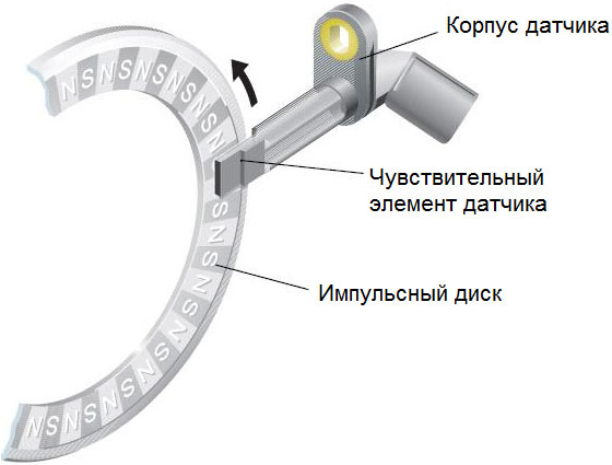
The sensitive element of the sensor is a "layer cake" of two or four thin permalloy plates (a special iron-nickel alloy), on which metal conductors are applied, distributing the magnetic field lines in a certain way. The plates and conductors are placed in an integrated circuit, which also houses the evaluation circuit to form the output signal. This chip is installed in a sensor located opposite the pulse rotor - a plastic ring with magnetized sections. The ring is rigidly mounted on the wheel hub.
The operation of AMR sensors boils down to the following. At rest, the resistance of the ferromagnetic plates of the sensor remains unchanged, so the output signal generated by the integrated circuit also does not change or is completely absent. While the car is moving, magnetized sections of the pulse ring pass by the sensor sensing element, which leads to some change in the direction of the magnetic field lines. This causes a change in the resistance of the permalloy plates, which is monitored by the evaluation circuit - as a result, a pulsed digital signal is generated at the output of the sensor, the frequency of which is proportional to the speed of the car.
It should be noted that magnetoresistive sensors allow you to track not only the speed of rotation of the wheels, but also the direction of their rotation and the moment of stopping. This is possible due to the presence of a pulse rotor with magnetized sections: the sensor monitors not only the change in the direction of the magnetic field, but also the sequence of passage of the magnetic poles past the sensing element.
DSAs of this type are the most reliable, they provide high accuracy in measuring the speed of rotation of the wheels and the effective operation of active vehicle safety systems.
The general principle of operation of speed sensors as part of ABS and other systems
Anti-lock braking systems, regardless of the sensors installed in them, have the same principle of operation. The ABS control unit monitors the signal coming from the speed sensors and compares it with pre-calculated indicators of the speed and acceleration of the vehicle (these indicators are individual for each car). If the signal from the sensor and the parameters recorded in the control unit coincide, the system is inactive. If the signal from one or more sensors deviates from the design parameters (that is, the wheels are blocked), then the system is included in the brake system, preventing the negative consequences of locking the wheels.
More information about the operation of anti-lock braking and other active car safety systems can be found in other articles on the site.
Post time: Aug-24-2023