
In most internal combustion engines, the gas distribution mechanism contains parts that ensure the transfer of force from the camshaft to the valves - pushers. Read all about valve tappets, their types, design and features of operation, as well as their selection and replacement, in this article.
What is a valve tappet?
The valve tappet is a part of the gas distribution mechanism of a piston internal combustion engine; timing tracking device, which transmits axial force from the camshaft to the valve directly or through auxiliary elements (rod, rocker arm).
The gas distribution mechanism of any internal combustion engine is generally based on three main parts: the camshaft, which rotates synchronously (but with half the angular velocity) with the crankshaft, valves and their drive. The actuator of the valve mechanism monitors the position of the camshaft and ensures the transfer of force from it to the valves. Various parts can be used as a drive: rods, rocker arms with and without rods, and others. In most timing, additional parts are also used - pushers.
Timing pushers perform a number of functions:
● They act as a link between the camshaft cam and other parts of the valve drive;
● Provide reliable transmission of forces from the camshaft cam to each of the valves;
● Evenly distribute the loads arising from the rotation of the camshaft and the operation of the timing;
● Increase the service life of timing parts and facilitate its maintenance;
● Pushers of certain types - provide the necessary temperature gaps between the timing parts and / or facilitate the process of their adjustment.
The valve tappet is an important part of the timing, in case of malfunction of which the engine operation deteriorates significantly. In the event of a breakdown, the pusher must be replaced, and in order to make the right choice of a new part, it is necessary to understand the existing types and designs of pushers.
Types and design of valve tappets
According to the design and principle of operation, pushers are divided into several types:
● Belleville;
● Cylindrical (piston);
● Roller;
● Hydraulic.
Each of the pushers has its own design features and applications.
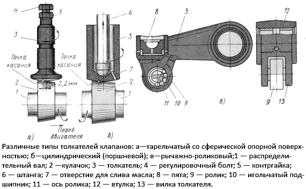
Different types of valve tappets
Poppet valve tappets
In general, such a pusher consists of a rod and a disc base, with which it rests on the camshaft cam. At the end of the rod there is a thread for installing an adjustment bolt with a locknut, through which the thermal gaps are adjusted. The supporting part of the pusher is subjected to heat treatment (carburization) in order to increase its wear resistance.
According to the shape of the supporting part (plate), these pushers are divided into two groups:
● With flat support;
● With spherical support.
Pushers of the first type work in tandem with a camshaft with cams with a cylindrical working surface. Pushers of the second type are used with camshafts with conical cams (with a beveled working surface) - due to this design, the pusher rotates during engine operation, which ensures its uniform wear.
Disc tappets are now practically not used, they were installed on engines with lower or lateral valves paired with or without rods.
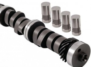
Cylindrical (piston) valve tappets
There are three main types of pushers of this type:
● Cylindrical hollow;
● Glasses under the barbell;
● Glasses under the valve.
In the first case, the pusher is made in the form of a closed cylinder, which, to facilitate the design, has cavities and windows inside. At one end there is a thread for an adjustment bolt with a locknut. Such pushers are rarely used today, as they are relatively massive and increase the dimensions of the entire timing.
In the second case, the pusher is made in the form of a glass of small diameter, inside of which a recess (heel) is made for the installation of the pusher rod. Windows can be made in the walls of the part to facilitate it and normal lubrication. Pushers of this type are still found on older power units with a lower camshaft.
In the third case, the pusher is made in the form of a glass of large diameter, inside of which a contact point is made for emphasis at the end of the valve stem. Usually, the pusher is thin-walled, its bottom and contact point are heat-treated (hardened or carburized). Such parts are widely used, they are installed in engines with an overhead camshaft and direct valve drive.
A type of cylindrical pusher for the valve is a pusher with an adjustment washer installed in the bottom (the camshaft cam rests against it). The washer can have a different thickness, its replacement is carried out by adjusting the thermal gaps.
Roller valve tappets
There are two main types of pushers of this type:
● End;
● Lever.
In the first case, the pusher is made in the form of a cylindrical rod, in the lower part of which a steel roller is installed through a needle bearing, and a recess (heel) for the rod is provided at the upper end. In the second case, the part is made in the form of a lever with one support, on the shoulder of which a roller is installed and there is a recess for the rod.
Devices of this type are most widely used in engines with a lower camshaft, they are practically not found on new power units.
Hydraulic valve tappets
Hydraulic pushers (hydraulic lifters) are the most modern solution that is used on many engines. Pushers of this type have a built-in hydraulic mechanism for adjusting thermal gaps, which automatically selects gaps and ensures normal operation of the motor.
The basis of the design of the pusher is the body (which simultaneously performs the functions of a plunger), made in the form of a wide glass. Inside the body is a movable cylinder with a check valve that divides the cylinder into two cavities. On the outer surface of the hydraulic lifter housing, a circular groove is made with holes for supplying oil to the cylinder from the engine lubrication system. The pusher is installed on the end face of the valve stem, while the groove on its body is aligned with the oil channel in the block head.
The hydraulic pusher works as follows. At the moment when the camshaft cam runs into the pusher, the cylinder experiences pressure from the valve and moves upwards, the check valve closes and locks the oil located inside the cylinder - the whole structure moves as a whole, ensuring the opening of the valve. At the moment of maximum pressure on the pusher, some of the oil can seep into the gaps between the cylinder and the pusher body, which leads to a change in the working clearances.
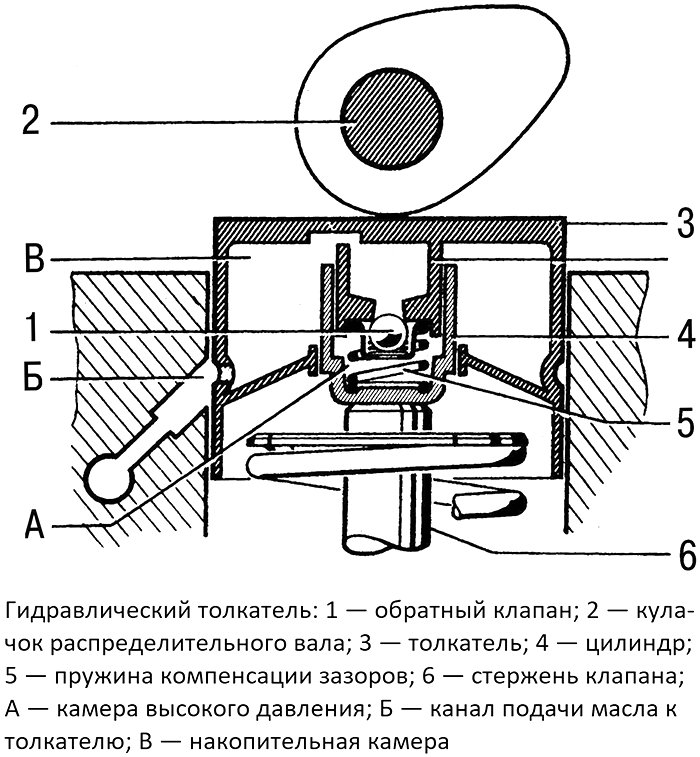
The design of the hydraulic pusher (hydraulic lifter)
When the cam escapes from the pusher, the valve rises and closes, at this moment the pusher body is opposite the oil channel in the cylinder head, and the pressure in the cylinder drops to almost zero. As a result, the oil coming from the head overcomes the spring force of the check valve and opens it, entering the cylinder (more precisely, into the discharge chamber inside it). Due to the pressure created, the pusher body rises (since the cylinder rests against the valve stem) and rests against the camshaft cam - this is how the gap is selected. In the future, the process is repeated.
During the operation of the engine, the surface of the tappets, camshaft cams and ends of the valve stems wear out and deform, and due to heating, the dimensions of other parts of the distribution mechanism change somewhat, which leads to an uncontrolled change in clearances. Hydraulic tappets compensate for these changes, always ensuring that there are no gaps and that the entire mechanism functions normally.
Issues of selection and replacement of valve tappets
Any pushers, despite the heat treatment of their working surfaces, wear out over time or malfunction, disrupting the operation of the engine. Problems with the pushers are manifested by the deterioration of the engine, including some change in the valve timing. Outwardly, these malfunctions are manifested by the characteristic noise of the motor, which is easily recognized by experienced craftsmen. However, in the case of engines with hydraulic lifters, noise immediately after starting is not a problem. The fact is that after the engine is idle, the oil leaves the tappets and head channels, and the first few seconds do not provide a choice of gaps - this is manifested by knocking. After a few seconds, the system is getting better and the noise disappears. If the noise is observed for more than 10-12 seconds, then you should pay attention to the condition of the pushers.
Defective pushers must be replaced with new ones of the same types and catalog numbers. Replacement should be carried out in accordance with the instructions for repair and maintenance of the car, this work is associated with partial disassembly of the cylinder head and requires the use of a special tool (for drying valves and others), so it is better to trust it to specialists. After replacing the pushers, it is periodically necessary to adjust the clearances, but if hydraulic components are used, then there is no need for maintenance.
Post time: Jul-14-2023