
In a vehicle with air brakes, a parking and spare (or auxiliary) brake control device is provided - a manual pneumatic crane. Read all about parking brake valves, their types, design and principles of operation, as well as the correct selection and replacement of these devices in the article.
What is a parking brake valve?
Parking brake valve (hand brake valve) - the control element of the brake system with a pneumatic drive; a hand crane designed to control vehicle release devices (spring energy accumulators) that are part of the parking and spare or auxiliary braking systems.
The parking and spare (and in some cases auxiliary) brakes of vehicles with pneumatic braking systems are built on the basis of spring energy accumulators (EA). EAs create the force necessary to press the brake pads against the drum due to the spring, and disinhibition is performed by supplying compressed air to the EA. This solution provides the possibility of braking even in the absence of compressed air in the system and creates conditions for the safe operation of the vehicle. The air supply to the EA is controlled manually by the driver using a special parking brake valve (or simply a manual air crane).
The parking brake valve has several functions:
● Supply of compressed air to the EA to release the car;
● Release of compressed air from the EA during braking. Moreover, both complete bleed of air when setting on the parking brake, and partial when the spare / auxiliary brake is operating;
● Checking the effectiveness of the parking brake of road trains (tractors with trailers).
The parking brake crane is one of the main controls of trucks, buses and other equipment with air brakes. Incorrect operation of this device or its breakdown can have tragic consequences, so a faulty crane must be repaired or replaced. To choose the right crane, you need to understand the existing types of these devices, their design and principle of operation.
Types, design and principle of operation of the parking brake crane
Parking brake valves differ in design and functionality (number of pins). By design, cranes are:
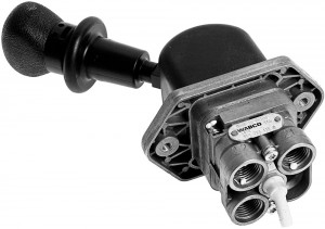
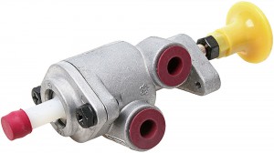
● With swivel control knob;
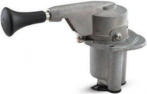
● With control lever.
Parking brake valve with swivel handle
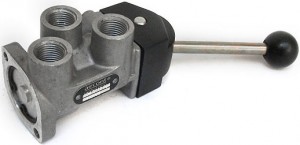
Parking brake valve with deflected handle
The operation of both types of cranes is based on similar principles, and the differences lie in the design of the drive and some control details - this is discussed below.
In terms of functionality, cranes are:
● To control the braking system of a single car or bus;
● To control the braking system of a road train (tractor with a trailer).
In the crane of the first type, only three outputs are provided, in the device of the second type - four. Also in cranes for road trains, it is possible to temporarily turn off the trailer brake system to check the performance of the parking brake of the tractor.
All parking brake valves are single-section, reverse action (since they provide air passage in only one direction - from the receivers to the EA, and from the EA to the atmosphere). The device includes a control valve, a piston-type tracking device, a valve actuator and a number of auxiliary elements. All parts are placed in a metal case with three or four leads:
● Supply from receivers (compressed air supply);
● Withdrawal to EA;
● Release into the atmosphere;
In cranes for road trains, the output to the brake control valve of the trailer / semi-trailer.
The crane drive, as mentioned above, can be built on the basis of a swivel handle or a deflected lever. In the first case, the valve stem is driven by a screw groove made inside the body cover, along which the guide cap moves when the handle is turned. When the handle is turned clockwise, the cap together with the stem is lowered, when turned counterclockwise, it rises, which provides valve control. There is also a stopper on the swivel cover, which, when the handle is turned, presses the additional brake check valve.
In the second case, the valve is controlled by a cam of a certain shape connected to the handle. When the handle is deflected in one direction or another, the cam presses on the valve stem or releases it, controlling the air flow. In both cases, the handles have a locking mechanism in extreme positions, the withdrawal from these positions is carried out by pulling the handle along its axis. And in cranes with a deflected handle, checking the performance of the parking brake is carried out, on the contrary, by pressing the handle along its axis.
The principle of operation of the parking brake valve in the general case is as follows. In the extreme fixed position of the handle, corresponding to the deactivated parking brake, the valve is positioned in such a way that the air from the receivers freely enters the EA, releasing the vehicle. When the parking brake is engaged, the handle is moved to the second fixed position, the valve redistributes the air flow in such a way that the air from the receivers is blocked, and the EAs communicate with the atmosphere - the pressure in them drops, the springs unclench and provide braking of the vehicle.
In the intermediate positions of the handle, the tracking device comes into operation - this ensures the functioning of the spare or auxiliary brake system. With a partial deflection of the handle from the EA, a certain amount of air is vented and the pads approach the brake drum - the necessary braking occurs. When the handle is stopped in this position (it is held by hand), a tracking device is triggered, which blocks the air line from the EA - the air ceases to bleed off and the pressure in the EA remains constant. With further movement of the handle in the same direction, the air from the EA is again bleed off and more intense braking occurs. When the handle moves in the opposite direction, air is supplied from the receivers to the EA, which leads to disinhibition of the car. Thus, the intensity of braking is proportional to the angle of deflection of the handle, which ensures comfortable control of the vehicle in case of a faulty service brake system or in other situations.
In cranes for road trains, it is possible to check the parking brake of the lever. Such a check is carried out by moving the handle to the appropriate position following the position of full braking (applying the parking brake), or by pressing it. In this case, a special valve provides pressure relief from the control line of the brake system of the trailer / semi-trailer, which leads to its release. As a result, the tractor remains braked only by EA springs, and the semi-trailer is completely disinhibited. Such a check allows you to evaluate the effectiveness of the parking brake of the tractor of the road train when parking on slopes or in other situations.
The parking brake valve is mounted on the dashboard of the car or on the floor of the cab next to the driver's seat (on the right hand), it is connected to the pneumatic system by three or four pipelines. Inscriptions are applied under the crane or on its body to avoid errors in the control of the brake system.
Issues of selection, replacement and maintenance of the parking brake crane
The parking brake valve during the operation of the car is constantly under high pressure and is exposed to various negative influences, so there is a high probability of malfunctions. Most often, guide caps, valves, springs and various sealing parts fail. A crane malfunction is diagnosed by incorrect operation of the entire parking system of the vehicle. Usually, in case of breakdowns of this unit, it is impossible to slow down or, conversely, release the car. Air leaks from the tap are also possible due to poor sealing of the junction of the terminals with pipelines, as well as the formation of cracks and breaks in the housing.
A faulty crane is dismantled from the car, disassembled and subjected to fault detection. If the problem is in the seals or in the cap, then the parts can be replaced - they are usually offered in repair kits. In case of more serious breakdowns, the crane changes in assembly. A device of the same type and model that was installed on the car earlier should be taken for replacement. It is unacceptable to install 3-lead cranes on tractors operated with trailers / semi-trailers, since it is impossible to organize the control of the trailer brake system with their help. Also, the crane must correspond to the old one in terms of operating pressure and installation dimensions.
Replacement of the crane is carried out in accordance with the instructions for the repair of the vehicle. During subsequent operation, this device is regularly checked, if necessary, the seals are replaced in it. The operation of the crane must comply with the procedure established by the vehicle manufacturer - only in this case the entire braking system will work efficiently and reliably in all conditions.
Post time: Jul-13-2023