
In vehicles with a hydraulic braking system, the main and wheel brake cylinders play a key role. Read about what a brake cylinder is, what types of cylinders there are, how they are arranged and work, as well as the correct selection, maintenance and repair of these parts in the article.
Brake cylinder - functions, types, features
Brake cylinder is the general name for the control and actuators of the brake systems of hydraulically driven vehicles. There are two devices that are different in design and purpose:
• Brake master cylinder (GTZ);
• Wheel (working) brake cylinders.
GTZ is the control element of the entire brake system, wheel cylinders are actuators that directly actuate the wheel brakes.
GTZ solves several problems:
• Conversion of mechanical force from the brake pedal into the pressure of the working fluid, which is sufficient to drive the actuators;
• Ensuring a constant level of working fluid in the system;
• Maintaining the performance of brakes in case of loss of tightness, leaks and in other situations;
• Facilitating driving (with brake booster).
The slave cylinders have one key function - the drive of the wheel brakes when braking the vehicle. Also, these components provide a partial return of the GTZ to its original position when the vehicle is released.
The number and location of the cylinders depends on the type of car and the number of axles. The brake master cylinder is one, but multi-section. The number of working cylinders can be equal to the number of wheels, twice or three times more (when installing two or three cylinders on the wheel).
The connection of wheel brakes to the GTZ depends on the type of vehicle drive.
In rear-wheel drive vehicles:
• First circuit - front wheels;
• The second circuit is the rear wheels.
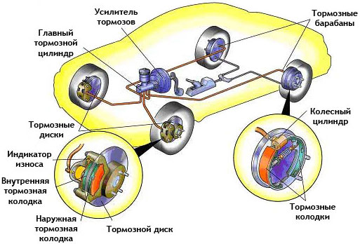
Typical diagram of the brake system of a car
A combined connection is possible: if there are two working cylinders on each front wheel, one of them is connected to the first circuit, the second to the second, it works together with the rear brakes.
In front-wheel drive vehicles:
• First circuit - right front and left rear wheels;
• Second circuit - left front and right rear wheels.
Other braking configurations may be used, but the above schemes are the most common.
The design and principle of operation of the brake master cylinder
Master brake cylinders are divided into two groups according to the number of circuits (sections):
• Single-circuit;
• Double-circuit.
Single-circuit cylinders are practically not used today, they can be found on some old cars. The vast majority of modern cars are equipped with dual-circuit GTZ - in fact, these are two cylinders in one body that work on autonomous brake circuits. The dual-circuit braking system is more efficient, reliable and safer.
Also, the master cylinders are divided into two groups according to the presence of a brake booster:
• Without amplifier;
• With vacuum brake booster.
Modern cars are equipped with a GTZ with an integrated vacuum brake booster, which facilitates control and increases the efficiency of the entire system.
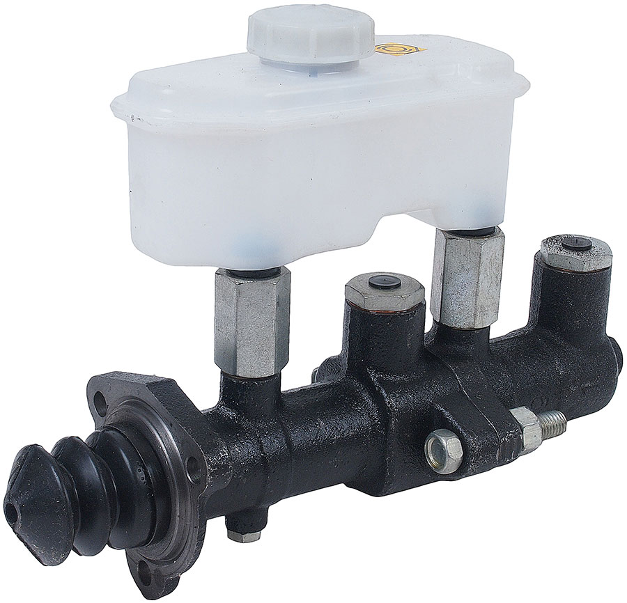
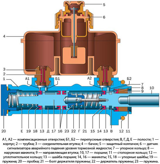
The design of the main brake booster is simple. It is based on a cast cylindrical body, in which there are two pistons installed one after the other - they form working sections. The front piston is connected by the rod to the brake booster or directly to the brake pedal, the rear piston does not have a rigid connection with the front, between them there is a short rod and a spring. In the upper part of the cylinder, above each section, there are bypass and compensation channels, and one or two pipes come out of each section for connection to the working circuits. A brake fluid reservoir is installed on the cylinder, it is connected to the sections using bypass and compensation channels.
GTZ functions as follows. When you press the brake pedal, the front piston shifts, it blocks the compensation channel, as a result of which the circuit becomes sealed and the pressure of the working fluid increases in it. The increase in pressure causes the rear piston to move, it also closes the compensation channel and compresses the working fluid. When the pistons are moving, the bypass channels in the cylinder always remain open, so the working fluid freely fills the cavities formed behind the pistons. As a result, the pressure in both circuits of the brake system increases, under the influence of this pressure, the wheel brake cylinders are triggered, pushing the pads - the vehicle slows down.
When the pedal leg is removed, the pistons tend to return to their original position (this is provided by the springs), and the return springs of the pads that compress the working cylinders also contribute to this. However, the working fluid entering the cavities behind the pistons in the GTZ through the bypass channels does not allow the pistons to instantly return to their original position - thanks to this, the release of the brakes is smooth, and the system works more reliably. When returning to the starting position, the pistons open the compensation channel, as a result of which the pressure in the working circuits is compared with atmospheric pressure. When the brake pedal is released, the working fluid from the reservoir freely enters the circuits, which compensates for the decrease in the amount of fluid due to leaks or for other reasons.
The design of the brake master cylinder ensures the operability of the system in case of leakage of working fluid in one of the circuits. If a leak occurs in the primary circuit, then the piston of the secondary circuit is driven directly from the piston of the primary circuit - a special rod is provided for this. If a leak occurs in the second circuit, then when you press the brake pedal, this piston rests on the end of the cylinder and provides an increase in fluid pressure in the primary circuit. In both cases, the pedal travel increases and the braking efficiency decreases slightly, so the malfunction must be eliminated as soon as possible.
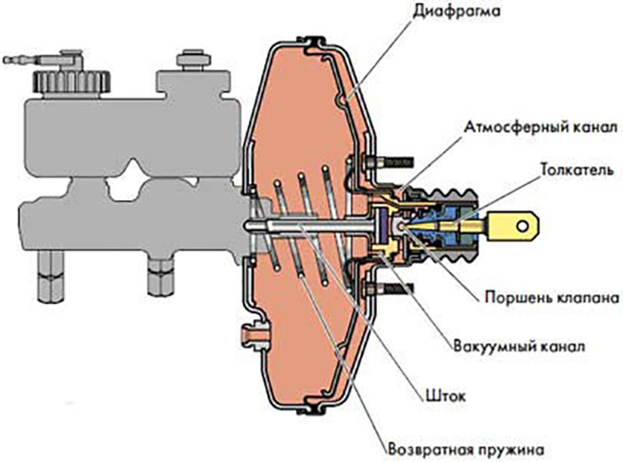
The vacuum brake booster also has a simple design. It is based on a sealed cylindrical body, divided by a membrane into two chambers - the rear vacuum and the front atmospheric. The vacuum chamber is connected to the engine intake manifold, so reduced pressure is created in it. The atmospheric chamber is connected by a channel to the vacuum, and it is also connected to the atmosphere. The chambers are separated by a valve mounted on the diaphragm, a rod passes through the entire amplifier, which is connected to the brake pedal on the one hand, and rests on the brake master cylinder on the other.
The principle of operation of the amplifier is as follows. When the pedal is not pressed, both chambers communicate through the valve, low pressure is observed in them, the entire assembly is inoperable. When force is applied to the pedal, the valve disconnects the chambers and at the same time connects the front chamber to the atmosphere - as a result, the pressure in it increases. Due to the pressure difference in the chambers, the diaphragm tends to move towards the vacuum chamber - this creates an additional force on the stem. In this way, the vacuum booster makes it easier to control the brakes by reducing the resistance of the pedal when you press it.
Design and principle of operation of wheel brake cylinders
Brake slave cylinders are divided into two types:
• For drum wheel brakes;
• For disc wheel brakes.
The slave cylinders in drum brakes are independent parts that are installed between the pads and ensure their extension during braking. The working cylinders of the disc brakes are integrated into the brake calipers, they provide pressure of the pads to the disc during braking. Structurally, these parts have significant differences.
The wheel brake cylinder of drum brakes in the simplest case is a tube (cast body) with pistons inserted from the ends, between which there is a cavity for the working fluid. On the outside, the pistons have thrust surfaces for connection with the pads, to protect against contamination, the pistons are closed with elastic caps. Also outside is a fitting for connection to the brake system.
The brake cylinder of disc brakes is a cylindrical cavity in the caliper into which a piston is inserted through the O-ring. On the reverse side of the piston there is a channel with a fitting for connection to the circuit of the brake system. The caliper can have from one to three cylinders of different diameters.
The wheel brake cylinders work simply. When braking, the pressure in the circuit increases, the working fluid enters the cylinder cavity and pushes the piston. The pistons of the drum brake cylinder are pushed in opposite directions, each of them drives its own pad. The caliper pistons come out of their cavities and press (directly or indirectly, through a special mechanism) the pad to the drum. When braking stops, the pressure in the circuit decreases and at some point the force of the return springs becomes sufficient to return the pistons to their original position - the vehicle is released.
Selection, replacement and maintenance of brake cylinders
When choosing the parts in question, it is necessary to strictly adhere to the recommendations of the vehicle manufacturer. When installing cylinders of a different model or type, the brakes may deteriorate, which is unacceptable.
During operation, the master and slave cylinders do not need special maintenance and serve without problems for many years. If the functioning of the brakes or the entire system deteriorates, it is necessary to diagnose the cylinders and, in case of their malfunction, simply replace them. Also, periodically you need to check the level of brake fluid in the reservoir and, if necessary, replenish it.
Post time: Aug-21-2023