
A number of modern trucks are equipped with dividers - special gearboxes that double the total number of transmission gears. The divider is controlled by a pneumatic valve - read about this valve, its design and functioning, as well as about the correct selection, replacement and maintenance of the valve in this article.
What is a divider actuation valve?
The divider actuation valve is a unit of the pneumomechanical gear shift system of the truck divider; a pneumatic valve that provides remote switching of the gearbox divider by supplying air to the distributor and the power pneumatic cylinder at the moment the clutch is completely disengaged.
In many models of domestic and foreign trucks, the gearbox is equipped with a divider - a single-stage gearbox, which doubles the total number of transmission gears. The divider significantly expands the capabilities of the gearbox, increasing the flexibility of driving in various road conditions and under different loads. The control of this unit on most vehicles is carried out by means of a pneumomechanical divider gear shift system, one of the important places in this system is occupied by the divider inclusion valve.
The divider actuation valve performs one key function: with its help, compressed air from the pneumatic system is supplied to the power pneumatic cylinder of the divider gear shift mechanism mounted on the gearbox crankcase. The valve is directly connected to the clutch actuator, which ensures that the divider gears are shifted when the clutch pedal is fully depressed and without additional manipulation on the driver's side. Incorrect operation of the valve or its failure partially or completely disrupts the operation of the divider, which requires repair. But before repairing or changing this valve, it is necessary to understand its design and features of functioning.
The device and principle of operation of the valves for switching on the divider
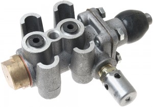
All divider valves used today have the same design in principle. The basis of the unit is a metal case with a longitudinal channel and elements for attaching the unit to the body or other parts of the car. At the rear of the body there is an intake valve, in the middle part there is a cavity with a valve stem, and in the front part the body is closed with a lid. The rod passes through the cover and extends beyond the housing, here it is covered with a dustproof rubber cover (dust fuse), in which a metal rod travel limiter is held. On the wall of the housing, opposite the intake valve and the cavity of the rod, there are inlet and outlet holes for connection to the pneumatic system. Also on the valve there is a breather with its own valve, which provides pressure relief when it grows excessively.
The divider actuation valve is located either next to the clutch pedal or next to the hydraulic/pneumatic-hydraulic clutch booster mechanism. In this case, the protruding part of the valve stem (on the side covered with a dust fuse) is opposite the stop on the clutch pedal or on the clutch fork drive pusher.
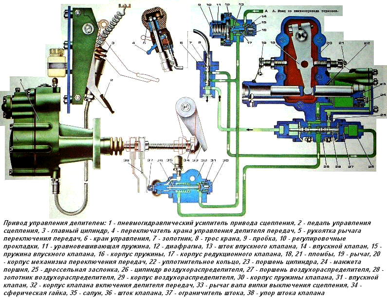
The valve is part of the divider's gear shift system, which also includes a control valve (on some cars this valve is controlled by a cable, in some it is built directly into the gear lever), an air distributor, a pressure reducing valve and a divider shift drive directly. The inlet of the valve is connected to the receiver (or a special valve that supplies air from the receiver), and the outlet is connected to the pneumatic cylinder of the divider actuator through the air distributor (and additionally through the pressure reducing valve, which prevents air leakage in the opposite direction).
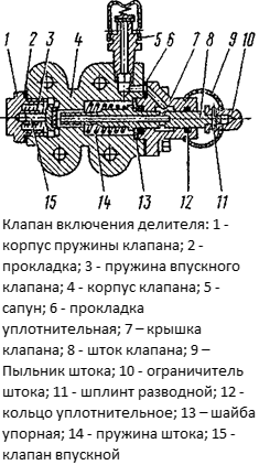
The design of the divider actuation valve
The valve in question and the entire pneumomechanical actuator of the divider work as follows. To engage the reduction or overdrive, the handle located on the gear lever is moved to the upper or lower position - this ensures the redistribution of air flows entering the air distributor (the control valve associated with the handle is responsible for this), its spool moves in one direction or the other. At the moment of maximum pressing of the clutch pedal, the divider actuation valve is triggered - its intake valve opens, and air enters the air distributor, and through it into the piston or piston cavity of the pneumatic cylinder. Due to the increase in pressure, the piston shifts to the side and pulls the lever behind it, which switches the divider to the highest or lowest gear. When the clutch is released, the valve closes and the divider continues to operate in the selected position. When switching the divider to another gear, the described processes are repeated, but the air flow from the valve is directed to the opposite cavity of the pneumatic cylinder. If the divider is not used when shifting gears, then its position does not change.
It is important to note here that the divider actuator valve opens only at the end of the pedal stroke, when the clutch is completely disengaged - this ensures normal gear changes without negative consequences for transmission parts. The moment the valve is turned on is regulated by the position of the tappet of its rod located on the pedal or on the clutch booster tappet.
It is also necessary to indicate that the divider inclusion valve is often called the control valves (switches) of the gear shift mechanism built into the lever. You need to understand that these are different devices that, although they work as part of the same system, perform different functions. This must be taken into account when buying spare parts and repairs.
How to properly select, replace and perform maintenance of the divider inclusion valve
During the operation of the vehicle, the entire divider control drive and its individual components, including the valve discussed here, are exposed to various negative influences - mechanical stress, pressure, the action of water vapor and oils contained in the air, etc. All this eventually leads to wear and breakage of the valve, which results in a deterioration in the operation of the system or in a complete loss of the ability to control the divider. A faulty valve must be dismantled, completely disassembled and subjected to fault detection, faulty parts can be replaced, and in case of significant breakdowns, it is better to change the valve assembly.
To repair the divider inclusion valve, you can use repair kits containing the most wear-prone parts - valve, springs, sealing elements. The repair kit must be purchased in accordance with the type and model of the valve.
Gear divider control drive
Only the type and model (respectively, the catalog number) that was installed on the vehicle by its manufacturer should be selected for replacement. For cars under warranty, this is the rule (when using non-original spare parts that differ from those recommended by the manufacturer, you can lose the warranty), and for older vehicles, it is quite possible to use analogues that have suitable installation dimensions and characteristics (working pressure).
Replacement of the divider actuator valve must be carried out in accordance with the repair and maintenance instructions for this particular vehicle. Usually, to perform this work, it is necessary to disconnect two pipelines from the valve and dismantle the valve itself, held by four (sometimes a different number) of bolts, and install the new valve in reverse order. Repairs should be carried out only after the pressure in the pneumatic system has been released.
After the valve is installed, its actuator is adjusted, which is ensured by changing the position of the rod stop located on the clutch pedal or booster rod. Usually, the adjustment is made in such a way that when the clutch pedal is fully depressed, there is a distance of 0.2-0.6 mm between the stem travel limiter and the end face of the valve cover (this is achieved by changing the position of the stem stop). This adjustment must also be performed at each routine maintenance of the pneumomechanical gear shift system of the divider. To make adjustments, remove the dust cover.
During subsequent operation, the valve is periodically removed, disassembled and checked, if necessary, it is washed and lubricated with a special grease composition. With the right selection and replacement, as well as with regular maintenance, the valve will serve for many years, providing confident control of the gearbox divider.
Post time: Jul-13-2023